EN Free Trial


Technical Support
Technical Articles
Smart200 and MR20 integrated IO configuration process
1、 System Overview
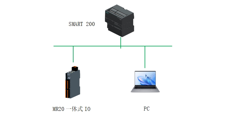
MR20 Integrated IO is a highly flexible integrated I/O system with numerous advantages (see figure below). This article mainly demonstrates the demonstration process of connecting MR20-PN-1616 with Siemens Smart200 controller

2、 Experimental materials
|
Serial number |
name |
Order number |
quantity |
brand |
remarks |
|
1 |
32 point integrated IO |
MR20-PN-1616 |
1 |
Mingda |
|
|
2 |
GSD file |
|
1 |
Mingda |
Official website download |
|
3 |
IP modification tool |
Gateway toolset v2.1.17.6 |
1 |
Mingda |
Official website download |
|
4 |
Smart200 |
6ES7288-1ST20-0AA1 |
1 |
Siemens |
|
|
5 |
configuration software |
STEP7-MicroWIN SMART |
1 |
Siemens |
|
|
6 |
Switching Mode Power Supply |
NDR-120-24 |
1 |
Mingwei |
3、 Configuration process
1. Configuration steps:
1. Connect SMART 200 and MR20-PN-1616
2. Install GSD file
3. Configure in STEP7 MicroWIN SMART
4. Connect the control power supply
5. Download the configuration to the controller
6. Check the LED indicator light
7. Test input and output signals
2. Install GSD files in STEP7 MicroWIN SMART

3. Click Browse, find the GSD file storage directory, select the corresponding GSD file, and click Open
4. Check the GSD file, click confirm, and install the GSD file.

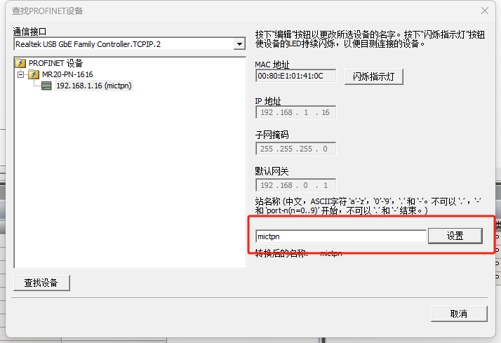
5. Assign device name: Open STEP 7-MicroWIN SMART, click on the tool, click on Find PROFINET device, search and select integrated IO, click on Settings, you can modify the device name as needed
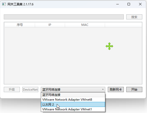
6. Modify IP address: Open the gateway toolset v2.1.17.6, select the corresponding physical network card, click start, and then click search in the upper right corner
Double click the searched device to enter the parameter setting interface
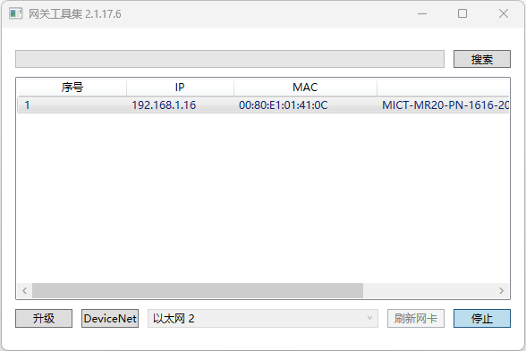
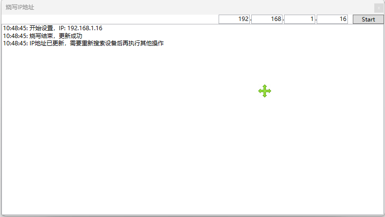
Click on 'Set IP' to modify the IP address as needed. Here, we have changed it to 192.168.1.16. Click on 'Start', and when the screen displays' Burn End 'and the update is successful, the IP address modification is complete

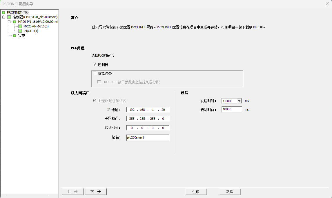
7. Open STEP 7-MicroWIN SMART, click on Tools, PROFINET
8. Select PLC role as controller, set IP address to 192.168.1.20, click next
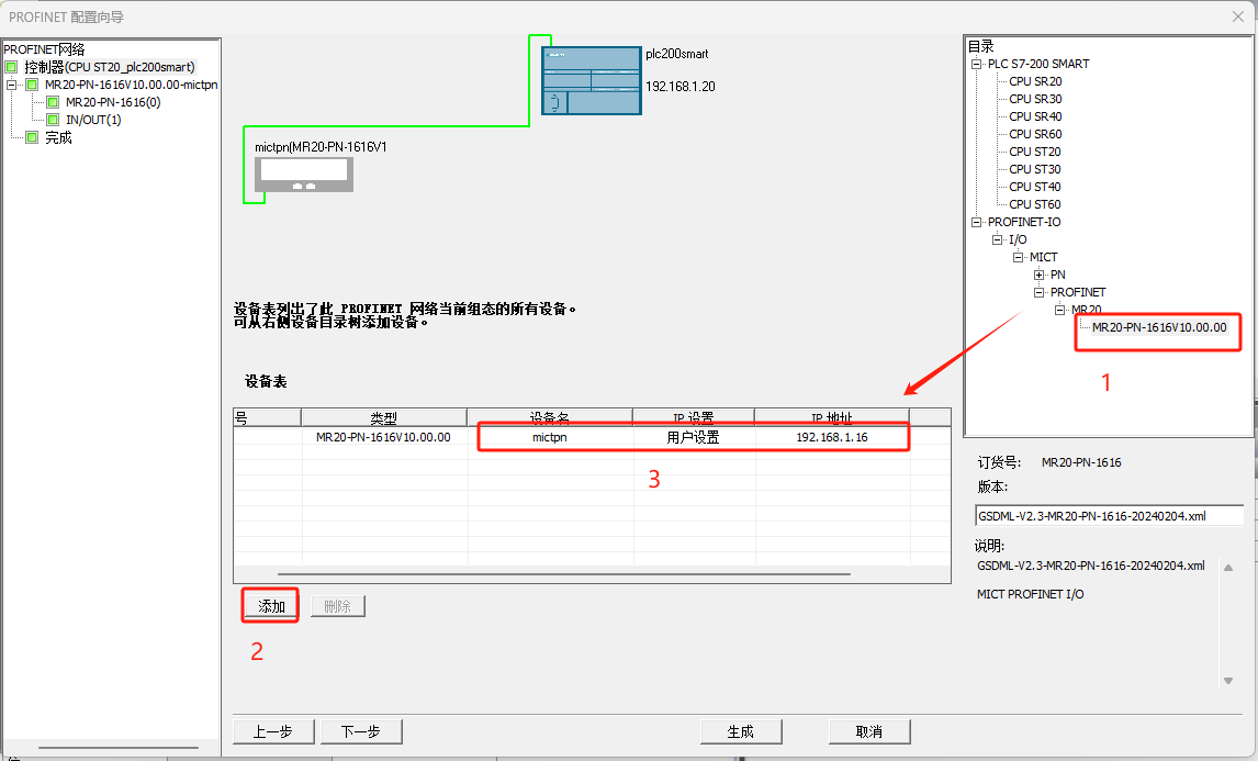
9. Find MR20-PN-1616 from the hardware directory, select the product, click add, and set the analyzed device name and IP address in 3 positions to maintain consistency with the actual settings.
10. Click next until you reach the address overview page, where we see that the addresses entered for the switch are: I128.0~I129.7; The output address of the switch is Q128.0~Q129.7. Click generate to complete the substation configuration.

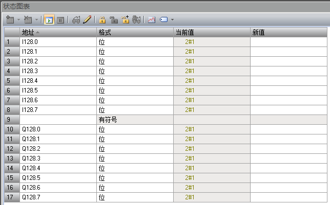
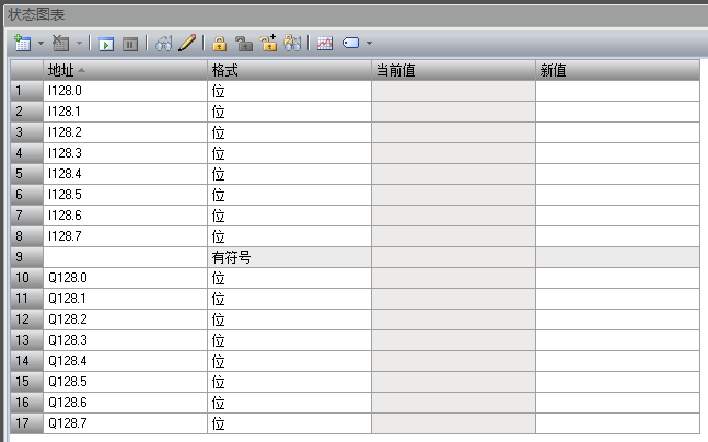
11. Create a monitoring list in the status chart, as shown below:
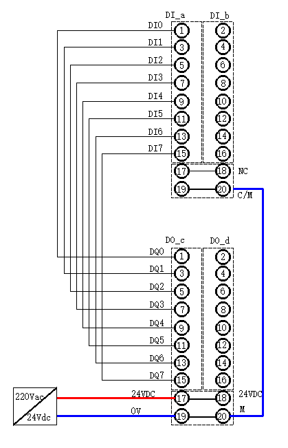
12. We will connect the MR20-PN-1616 wiring diagram as follows
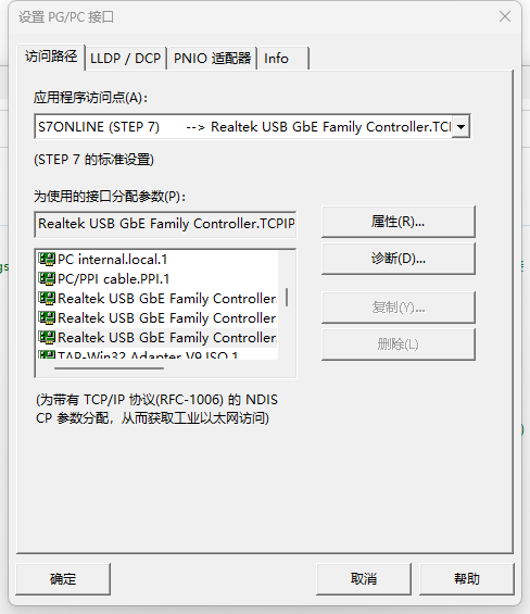
13. Set PG/PC interface, download program
12. Click on communication to find CPU
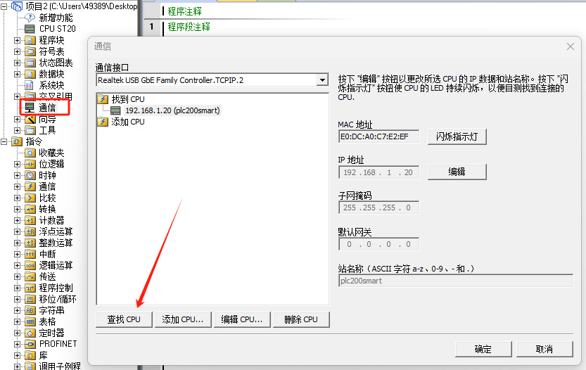
13. Click Download to download the configuration and program to the CPU

4、 Configuration testing
Open the status chart and fill in the addresses that need to be monitored. Here, use I128.0~I128.7, Q128.0~Q128.7. Monitor the status of the switch input point by controlling the switch output point to check if the function is working properly.
