EN Free Trial


Technical Support
Technical Articles
The configuration process of S7-300 and MR30 distributed IO in Boruto V19
1、 System Overview
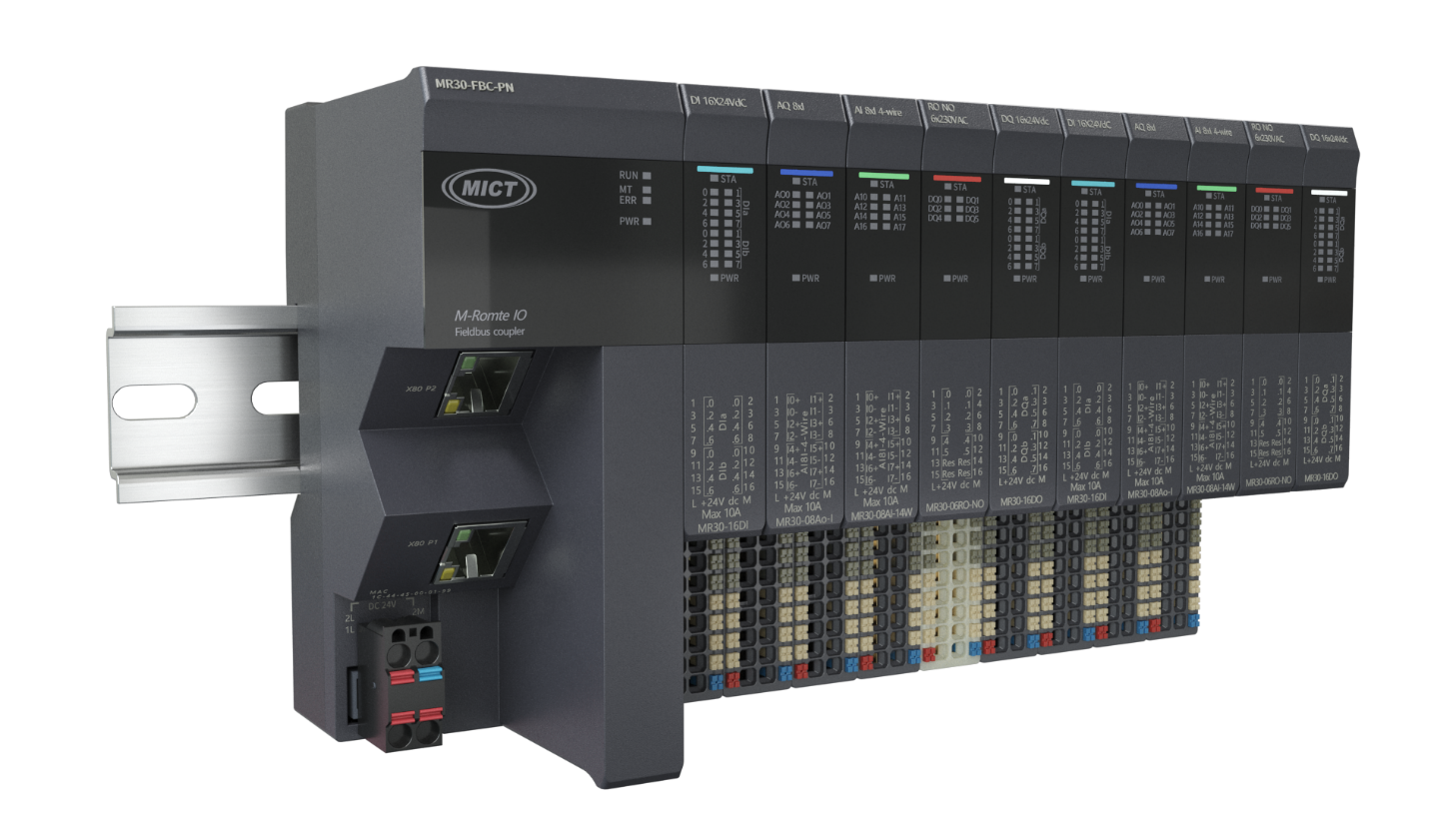
MR30 Distributed IO is a highly flexible and scalable distributed I/O system, and MR30-FBC-PN is used to connect process signals to the higher-level controller through the PROFINET bus.
2、 Experimental materials
|
Serial number |
Name |
Order number |
Quantity |
Brand |
Remarks |
|
1 |
coupler |
MR30-FBC-PN |
1 |
Mingda |
|
|
2 |
Switch input module |
MR30-16DI |
1 |
Mingda |
|
|
3 |
Switching output module |
MR30-16DO |
1 |
Mingda |
|
|
4 |
Analog input module |
MR30-08AI-I4W |
1 |
Mingda |
|
|
5 |
Analog output module |
MR30-08AO-I |
1 |
Mingda |
|
|
6 |
Analog input module |
MR30-08AI-U |
1 |
Mingda |
|
|
7 |
Analog output module |
MR30-08AO-U |
1 |
Mingda |
|
|
8 |
CPU314C-2 PN/DP |
6ES7 314-6EH04-0AB0 |
1 |
Mingda |
|
|
7 |
Switching Mode Power Supply |
NDR-120-24 |
1 |
Mingwei |
|
|
8 |
configuration software |
STEP7 Professional V19 |
1 |
Siemens |
|
|
9 |
GSD file |
GSDML-V2.42-MICT-PN-20240620 |
1 |
Mingda |
3、 Configuration process
1. Configuration steps:
1. Install MR30-FBC-PN
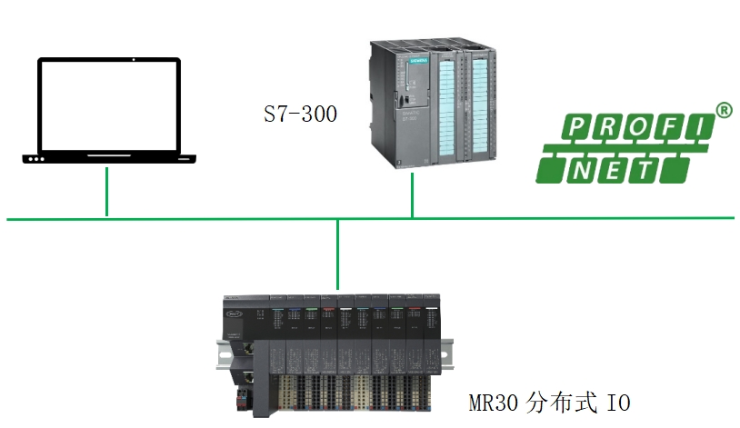
2. Connect CPU 314C-2 PN/DP and MR30-FBC-PN
3. Install GSD file
4. Configuring in STEP7 Professional V19
5. Connect the control power supply
6. Download the configuration to the controller
7. Check the LED indicator light
8. Test input and output signals
2. Click on the option - Manage General Station Description Files (GSD) during the process of browsing

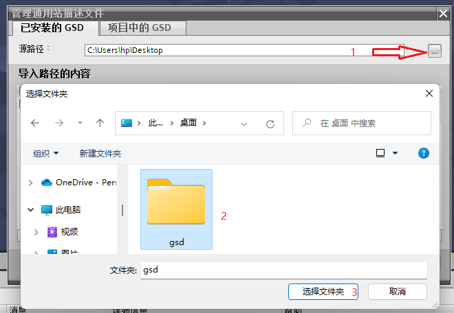
3. Click Browse, find the GSD file storage directory, and select the folder
4. Select the GSD file and click Install

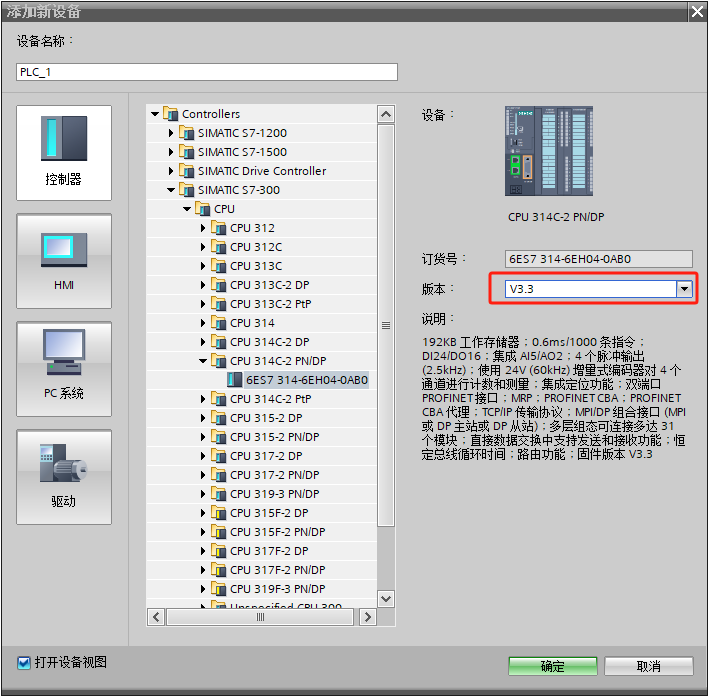
5. Open the Botu software, create a new project, click on Add New Device, select CPU314C-2 PN/DP with firmware version 3.3, and click OK.
6. Switch the hardware configuration interface to the network view, find the directory of MR30 in the hardware directory on the right, drag and drop the coupler to the network view, assign MR30 to the CPU14C-2 PN/DP controller, set the IP addresses of CPU14C-2 PN/DP and coupler respectively, which are 192.168.1.130 and 192.168.1.30, and assign the device names PLC_300 and mr30 pncoupler.

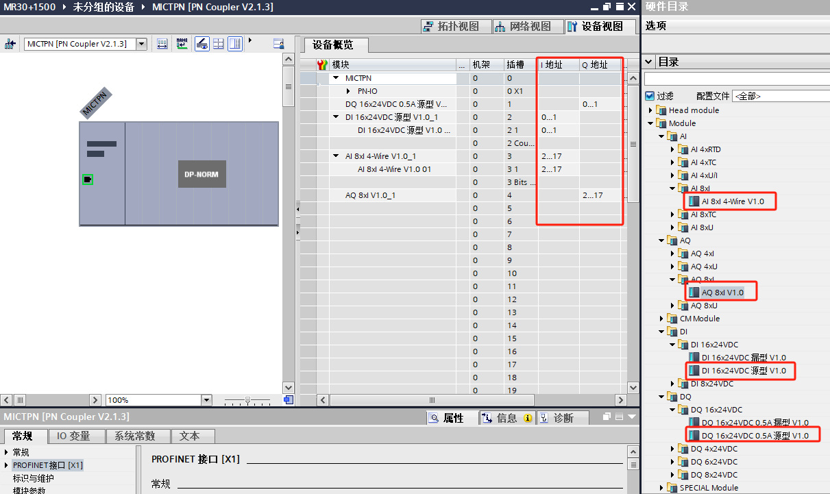
7. Double click the coupler to enter the device view. In the hardware directory on the right, select the corresponding module and load it into the module list. You can modify the module address at the I and Q addresses. Note that the default process image area of the 300 series CPU is shown in the following figure. Method 1: Increase the process image area of the CPU and adjust it according to the IO address, ideally including the maximum IO address; Method 2: Adjust the IO module address, and adjust the maximum address area to be within the CPU process image area.

9. All IO module diagnostics include: power supply voltage L+missing, and filtering can be set as needed for each channel of the switch input module, as shown in the following figure
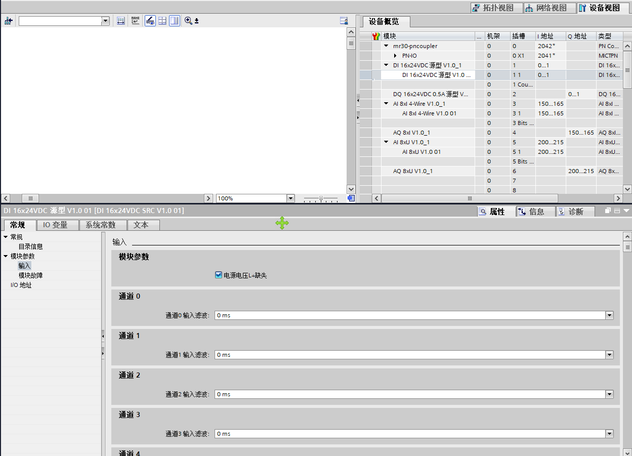
10. The switch output module can be configured for safe output, and can be configured as follows as needed: retain the previous value; Output 0; Output 1

10. The analog input/output module block can be set as needed as follows
Set output format: large end mode, small end mode;
Diagnostic types: overflow diagnosis, underflow diagnosis, open circuit diagnosis;
Channel type: 0-20mA, 4-20mA
Anti interference settings: None, 5Hz, 10Hz, 15 Hz, 25 Hz, 30 Hz, 50 Hz, 60 Hz.
Filter setting: K=0 K=4 K=8 K=16

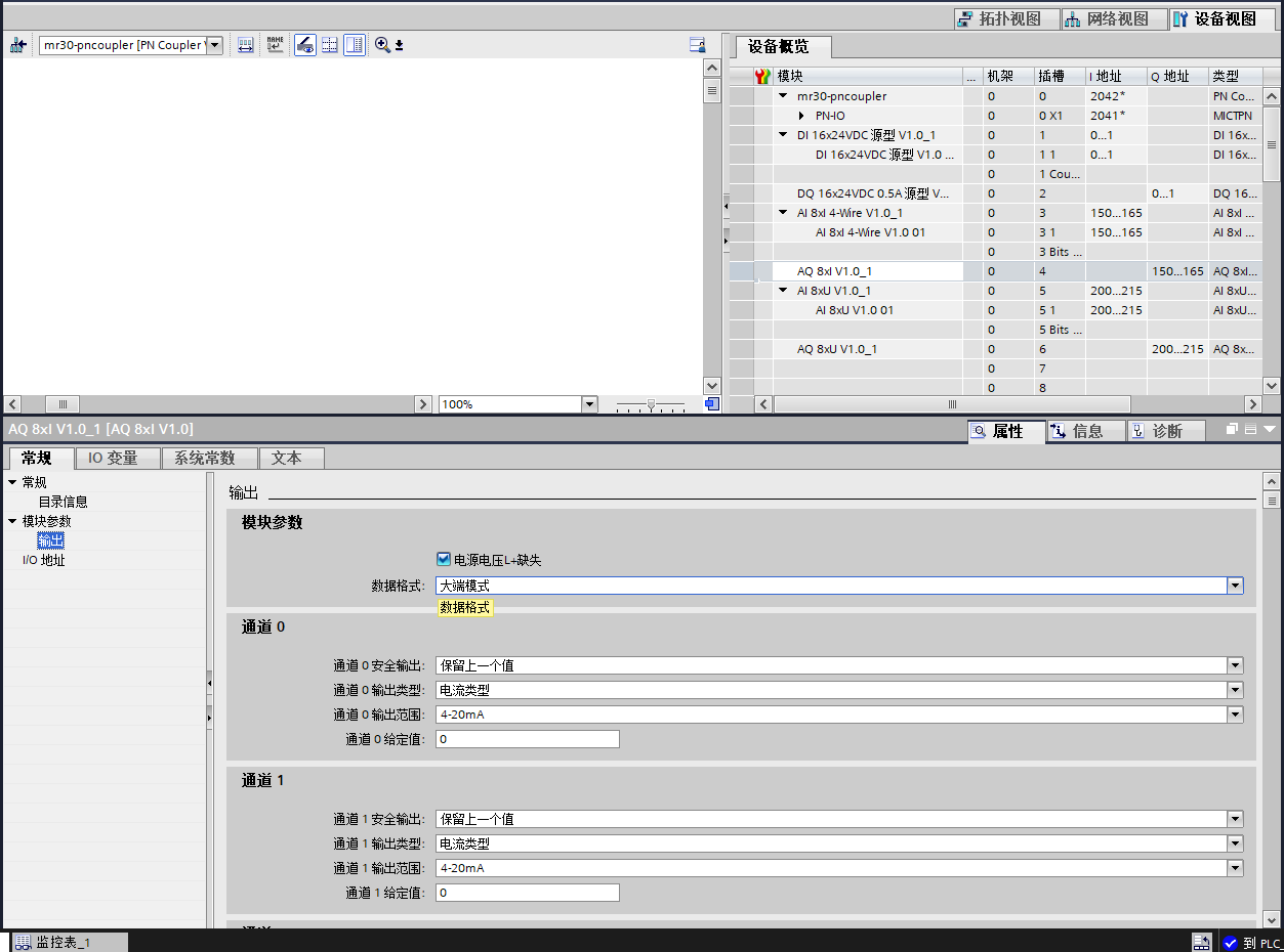
12. The analog output module can be set as follows, which can be adjusted as needed
Data format: Large end mode, Small end mode
Safe output: Keep the previous value, output 0, output the given value. When selecting to output the given value, the corresponding numerical value needs to be filled in the given value of the corresponding channel.
Output range: 0-20mA, 4-20mA
Output type: disabled, current type
4、 Configuration testing
1. Panel design, viewing method selection: small icon, choose to set PG/PC interface, select the corresponding network card
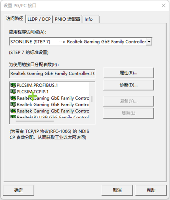
2. Click to download the program

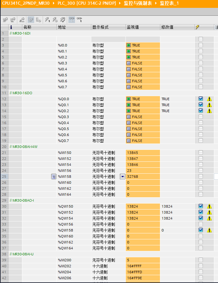
3. Click on the monitoring and mandatory list to add a new monitoring table, as shown in the following figure. Our monitoring address here is:
I0.0~I0.7,Q0.0~Q0.7 IW150~IW164,QW150~QW164
The wiring diagram is as follows. We will connect channels Q0.0~Q0.7 and I0.0~I0.7 accordingly
Wiring corresponding to channels QW150~QW164 and IW150~IW164

We only need to give corresponding values to Q0.0~Q0.7 and QW150~QW164, and observe the status values through I0.0~I0.7 and IW150~IW164. If the input value corresponds to the output value, the test is normal.
